MSI Logic Circuits

Q1:
It is suspected that the comparator in the figure given below has a problem. The inputs are activated in the table shown below and the corresponding outputs noted. What is most likely wrong with the circuit?
For P0 – P3 = 1 and Q0 – Q3 = 0, P > Q = 1, P = Q = 1, P < Q = 0
For P0 – P3 = 0 and Q0 – Q3 = 1, P > Q = 0, P = Q = 1, P < Q = 1
For P0 – P3 = 1 and Q0 – Q3 = 1, P > Q = 0, P = Q = 1, P < Q = 0
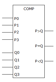
A The P0–P3 inputs are defective.

B One or more of the Q inputs is bad.

C The P = Q output is shorted to Vcc.

D Nothing is wrong; the circuit is functioning properly.

ANS:C - The P = Q output is shorted to Vcc.

No answer description is available.


img not found
img

For help Students Orientation
Mcqs Questions

One stop destination for examination, preparation, recruitment, and more. Specially designed online test to solve all your preparation worries. Go wherever you want to and practice whenever you want, using the online test platform.