MSI Logic Circuits

Q1:
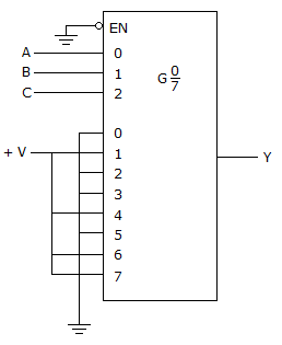
Refer to the figure given below. The logic function generator being implemented with the multiplexer in this circuit produces a constant LOW on the output. The ABC inputs are checked and appear to be pulsing; also, the 0–7 and EN inputs are checked with the scope and all appear to be at 0 V. A check with the DMM confirms that power is on. What is the problem, and what should be done to correct it?

A The output is shorted to Vcc; replace the IC.

B The scope's vertical input is in the AC mode and the common connection for the 0,2,3 and 5 inputs is bad. Set the scope's vertical input mode to DC, and repair the bad solder connection.

C Power has not been applied to the circuit; apply power.

D The output is shorted to ground; replace the IC.

ANS:B - The scope's vertical input is in the AC mode and the common connection for the 0,2,3 and 5 inputs is bad. Set the scope's vertical input mode to DC, and repair the bad solder connection.

No answer description is available.


img not found
img

For help Students Orientation
Mcqs Questions

One stop destination for examination, preparation, recruitment, and more. Specially designed online test to solve all your preparation worries. Go wherever you want to and practice whenever you want, using the online test platform.