Memory and Storage - Technical MCQs

Q1:

Refer to the given figures (a) and (b). A logic analyzer is used to check the circuit in figure (a) and displays the waveforms shown in figure (b). The actual analyzer display shows all four data outputs, Q0-Q3. The analyzer's cursor is placed at position X and all four of the data output lines show a LOW level output. What is wrong, if anything, with the circuit?

A Nothing is wrong, according to the display. The outputs are in the open state and should show zero output voltage.

B The circuit is in the READ mode and the outputs, Q0-Q3, should reflect the contents of the memory at that address. The chip is defective; replace the chip.

C The circuit is in the  
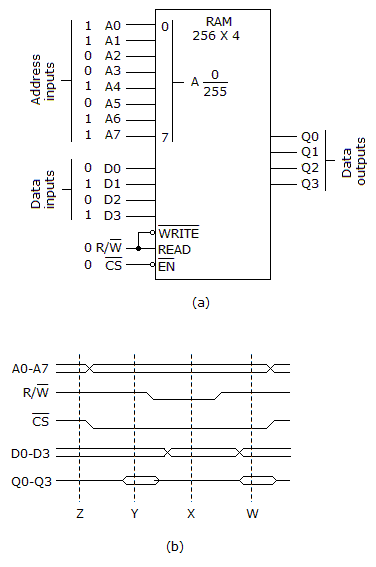
mode and should be writing the contents of the selected address to Q0–Q3.

D The Q0–Q3 lines can be either LOW or HIGH, since the chip is in the tristate mode in which case their level is unpredictable.

ANS:A - Nothing is wrong, according to the display. The outputs are in the open state and should show zero output voltage.

No answer description is available.